
EASY STEPPERS
HARDWARE
The main intelligence and effort of the project lies in the software. Still hardware is essential to decode the data through the parallel port and to drive the stepper motors.
In parallel port, data is send as 8 bits. This eight bits is divided into 2 for getting 4 + 4 bits. The first four bits of the parallel port is used to select the motor. The maximum possible arrangements using the four bits is sixteen. So the project can support sixteen stepper motors. By changing the bit pattern we can select the desired stepper motor. The second four bits is used to transfer the data for selected stepper motor. For more details about parallel port go to the studies page.
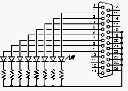
I think you have already downloaded the Easysteppers software. If not, go to software section and down load the Easysteppers. First of all you should test the Easysteppers. So you should make a testport. The circuit to test the Easysteppers is shown below (no PCBs).

Use a printer cable and cut out the unwanted wires.Use 470 ohm resistors and small LEDs (I used 10ma LEDs and didn't used the resistors). Check the wire connections twice.
Connect the testport to the parallel port behind your machine. Run the Easysteppers. Click the port button in the menubar of the Easysteppers. Then press testport button. If the LEDs are binking the settings are OK.
Now you did the first step into the reality of robotics. The next step is to make the decoding circuit. This circuit decodes the data comming through the parallel port and driving the stepper motors. Details below.
Now you did the first step into the reality of robotics. The next step is to make the decoding circuit. This circuit decodes the data comming through the parallel port and driving the stepper motors. Details below.

I four bit
The parallel port is using 8 bit data transfer. In EASY STEPPERS, this 8 bit data from the parallel port is divided into two, 4 bit + 4 bit. One 4 bit data is using to select the desired stepper motor and the second 4 bit is used to transfer the position data into the stepper motor.
II four bit
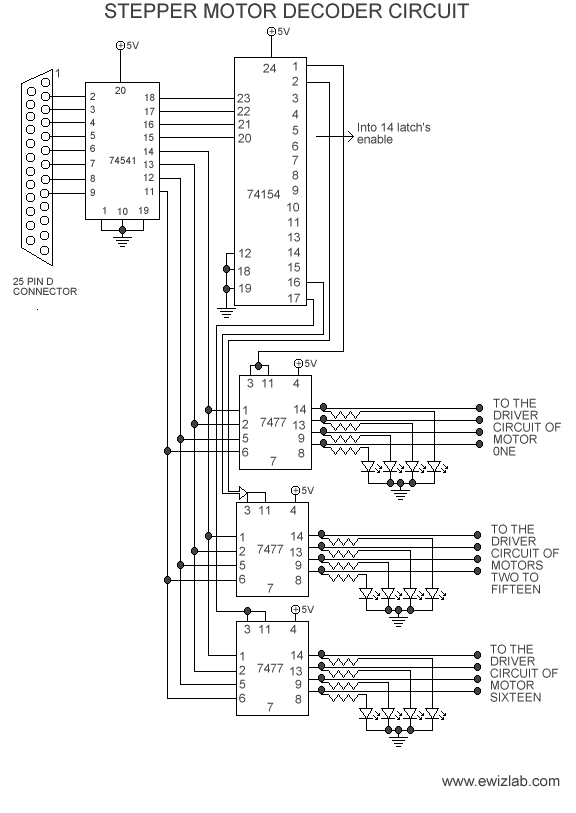
16 latchs are used. Only 3 is shown
In the circuit three ICs are used. One buffer IC, One decoder IC and 16 Latchs. For details about the ICs go to the datasheets page.
In the circuit the data from the parallel port is given into the octal buffer through 25 pin 'D' connector. The first four bits is given into 4 to 16 decoder and the next four bits is given commenly into 16 latchs. The output of the 4 to 16 decoder is given into the enable pin of the latches. A type of software scanning is going on, in the program.
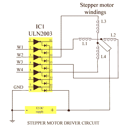
If you made the decoding circuit then you should make driver circuits and power supplies.

www.electrogenes.com