
CIRCUITS
POWERFULL FM TRANSMITTER.
100 MHz : 2 WATTS : 15 KM RANGE
100 MHz : 2 WATTS : 15 KM RANGE

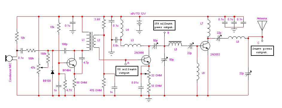
Assemble the circuit on a good-quality glass epoxy board and house the transmitter inside an aluminium case. Shield the oscillator stage using an aluminium sheet. Potentiometer 47k is used to set the center frequency where as potentiometer 22 OHM is used as power control. 2N3866 and 2N3553 must be mounted on a heatsink. Do not switch on the transmitter without a matching anteena. Adjust potentiometer 47k to set the center frequency near 100MHz With a good matching 50-OHM ground plane anteena or multi-element Yagi anteena, this transmitter can provide reasonably good signal strength up to a distance of about 15 km.
Coil winding details:
L1 - 4 turns of 20 SWG wire close wound over 8mm diameter plastic former
L2 - 2 turns of 24 SWG wire near top end of L1
(Note: No core (i.e. air core)is used for above coils)
L3 - 7 turns of 24 SWG wire close wound with 3mm diameter air core.
L4 - 7 turns of 24 SWG wire-wound on a ferrite bead (as choke)
USEFUL TIP :
Calibrating any Transmitters:
Connect a 6V rating bulb on the output of the transmitter. Now adjust the trimmers or inducters available in the transmitter until the bulb produecing maximum luminisence.
In the transmitter mentioned above, first adjust 50p trimmers and then 22p trimmers for the maximum luminisence of the connected bulb.
Ref : EFY
www.ewizlab.com