
Design Center
Parallel Port Interfacing
PC parallel port is the easiest I/O channel for connecting your own circuits to PC. The port can be easily interfaced when you first understand some basic idea. EasySteppers software is making use of the parallel port
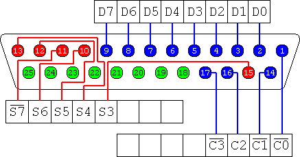
PC parallel port is 25 pin D-shaped female connector of the computer. It is usually used for connecting computer to printer. All 25 pins are not needed for the interfacing porpose. We can use 8 output pins (data lines), 9 input pins and a signal ground. It is presented in the figure below and in the table below. Those output pins are adequate for all hobby purposes.
PC parallel port is 25 pin D-shaped female connector of the computer. It is usually used for connecting computer to printer. All 25 pins are not needed for the interfacing porpose. We can use 8 output pins (data lines), 9 input pins and a signal ground. It is presented in the figure below and in the table below. Those output pins are adequate for all hobby purposes.
Pin Function
2 D0
3 D1
4 D2
5 D3
6 D4
7 D5
8 D6
9 D7
10 S6
11 S7
12 S5
13 S4
15 S3
01 C0
14 C1
16 C2
17 C3
2 D0
3 D1
4 D2
5 D3
6 D4
7 D5
8 D6
9 D7
10 S6
11 S7
12 S5
13 S4
15 S3
01 C0
14 C1
16 C2
17 C3

Parallel port pinout connector shown as it is viewed from the back side of computer
Pins 18,19,20,21,22,23,24 and 25 are all ground pins.
The data pins are TTL level output pins. This means that they put out ideally 0V when they are in low logic level (0) and +5V when they are in high logic level (1). The output current capacity of the parallel port is limited to only few milliamperes.
The data pins are TTL level output pins. This means that they put out ideally 0V when they are in low logic level (0) and +5V when they are in high logic level (1). The output current capacity of the parallel port is limited to only few milliamperes.
www.ewizlab.com